Understanding Voltage Drop: Principles, Formula, and International Standards
Voltage drop is the reduction in voltage as electric current flows through a conductor. This phenomenon is governed by Ohm’s Law and is expressed as: V = I × R = I × (ρ × L / A), where V is voltage drop, I is current (A), ρ is resistivity (Ω·m), L is cable length (m), and A is cross-sectional area (mm²). Various international standards limit allowable voltage drop to prevent power loss and equipment malfunction. IEC 60364 recommends a maximum voltage drop of 5% for power circuits and 3% for lighting circuits. In comparison, the NEC (National Electrical Code) suggests a total maximum of 5% across feeder and branch circuits. For instance, for a 400V supply system, a 5% drop equals 20V, which can critically affect sensitive devices. Excessive drop causes overheating, energy waste, and potential failure of electrical systems. Compliance with these standards is essential for safe and efficient design.
How to Select the Correct Cable Cross-sectional Area
Selecting the correct cable size balances voltage performance and material cost. The minimum cross-sectional area A can be determined using the rearranged voltage drop formula: A = (ρ × L × I) / V. Consider a 50-meter run carrying 80A using copper (ρ = 1.72 × 10⁻⁸ Ω·m), with a max allowable drop of 10V. Plugging into the formula gives A ≈ 34.4 mm². In practice, we round up to the next standard size (e.g., 35 mm²). Engineers must also account for derating factors (e.g., ambient temperature, grouping) and future expansion. While oversizing reduces losses, it raises costs. For balanced design:
- Step 1: Calculate load current (I)
- Step 2: Define allowable voltage drop (V)
- Step 3: Determine cable length (L)
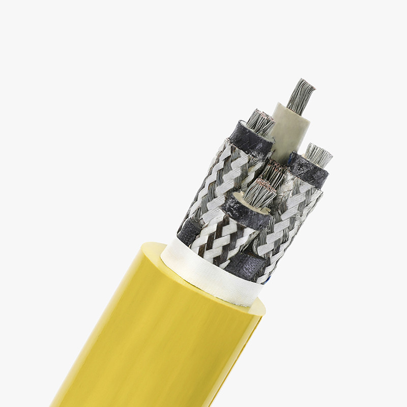
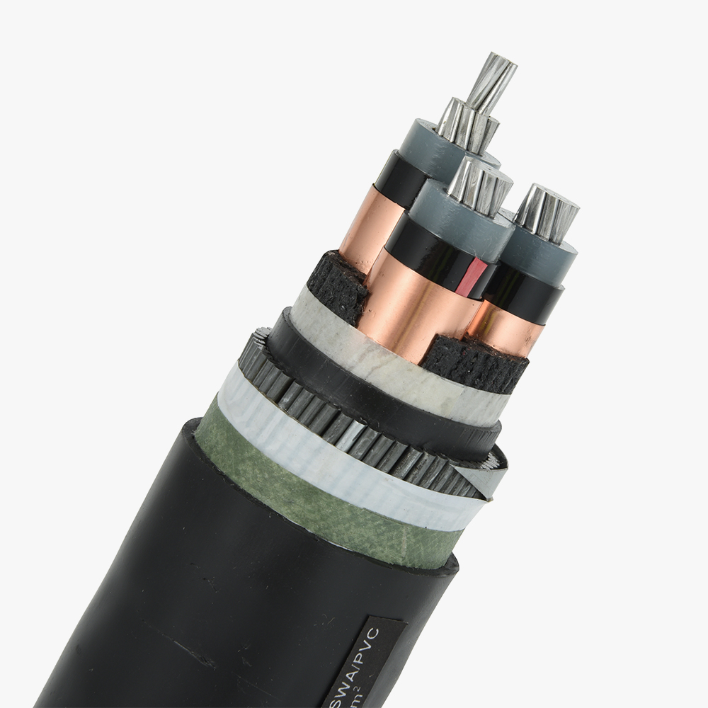
- Step 4: Choose material (ρ for Cu or Al)
- Step 5: Calculate A and select closest standard cable size
A data-driven approach ensures long-term energy efficiency without unnecessary expenditure.
Impact of Cable Length on Voltage Drop
Cable length directly affects voltage drop. Doubling the length doubles the resistance and hence the voltage drop. For example, with an 80A load over 25 meters, a 10 mm² copper cable may drop 6V; over 50 meters, the drop becomes 12V—potentially breaching standard limits. Hence, length optimization is critical in design.
Economic vs. Technical Cross-sectional Area: Balancing Performance and Cost
Two main approaches are used in practice:
1. Technical Cross-sectional Area — based on limiting voltage drop, ensuring regulatory compliance. It typically leads to larger cable sizes.
2. Economic Cross-sectional Area — based on the current density method, which optimizes cable size using cost-benefit analysis. The typical formula: J = I / A (where J is current density). A density of 2.5–5 A/mm² is standard for copper.
Consider a 100A circuit over 100m. The technical method may suggest 50 mm² to limit voltage drop, while the economic method (based on life cycle cost, losses, and material price) may favor 35 mm² if annual energy losses are acceptable.
A Total Cost of Ownership (TCO) analysis includes:
- Initial purchase cost
- Annual energy loss (calculated using I²R)
- Maintenance cost over lifetime
By comparing both methods, customers can choose either lower upfront investment or long-term operational savings depending on the project’s priority.
Application Examples
Technical sizing is often used in hospitals and data centers for critical loads. Economic sizing suits industrial settings where efficiency and cost trade-offs are acceptable, such as factory lighting circuits.