The physical significance and derivation formula of characteristic impedance (typically 50Ω/75Ω)
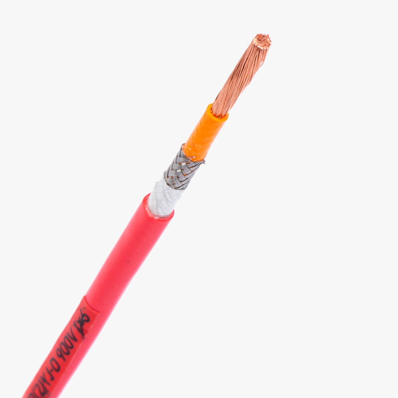
Characteristic impedance is a key electrical parameter of coaxial cables, representing the ratio of voltage to current in a signal-carrying line under steady-state conditions. It affects signal transmission efficiency, reflection, and loss. The formula for characteristic impedance (Z0) of a coaxial cable is derived as:
Z0 = (60/√εr) × ln(D/d),
where εr is the dielectric constant, D is the inner diameter of the shield, and d is the outer diameter of the inner conductor.

Why does the foam density of the insulation layer and the concentricity of the conductor affect impedance stability?
The foam insulation layer in coaxial cables contains gas-filled voids that lower the dielectric constant (εr), enhancing high-frequency signal transmission. However, if the foam density is inconsistent, the dielectric constant fluctuates, causing impedance variation along the cable length. Similarly, conductor concentricity—the uniform spacing between the inner conductor and outer shield—is crucial. Any off-center deviation alters the effective diameter ratio (D/d), directly impacting the characteristic impedance per the formula. Even minor concentricity issues can lead to signal reflections, degradation, or mismatched transmission, especially in high-speed and high-frequency applications. Thus, precise control of both foam density and concentricity is essential for maintaining consistent impedance.

Challenges of impedance control processes
Achieving precise impedance control in coaxial cables presents several manufacturing challenges. First, maintaining consistent foam density during extrusion requires tight process control, as even minor gas pressure or temperature fluctuations can impact insulation uniformity. Second, achieving excellent conductor concentricity demands high-precision alignment during conductor feeding and jacketing. Variations here directly disrupt impedance uniformity. Third, material batch differences—such as copper purity or dielectric consistency—can subtly alter the cable’s electromagnetic properties. Additionally, during long production runs, mechanical wear or environmental changes can lead to gradual drift in parameters. All these factors require real-time monitoring and feedback systems to ensure that impedance remains within strict tolerance limits.
Demand for coaxial cables with impedance control across various industries
Precision impedance control is critical in industries such as telecommunications, aerospace, defense, medical imaging, and broadcasting. In these fields, signal integrity, high-frequency performance, and electromagnetic compatibility are essential. Coaxial cables with controlled impedance ensure low-loss transmission and reduced signal reflection, enabling reliable operation in mission-critical systems.
Strict impedance control increases costs but reduces failure rates. Differences between consumer-grade (±10%) and military-grade (±2%) applications
Tighter impedance control requires more advanced production techniques and quality testing, leading to increased costs. However, it significantly reduces signal degradation and equipment failures. Consumer-grade cables generally allow ±10% variation, which is sufficient for basic applications. In contrast, military and aerospace systems often demand ±2% precision to guarantee optimal signal fidelity, especially under harsh environmental conditions.
Recommendations for customers
Choose impedance tolerance based on application requirements. For high-reliability systems, invest in cables with tighter control and verified certifications.